One of the most common questions we get asked during The Retro Roundtable podcast is “What is the proper way to generate CSYNC from HSYNC and VSYNC?”. People understandably ask this because we’ve mentioned several times that nearly all implementations of this process are incorrect. The question is typically asked with the expectation that it can be quickly answered. I mean, if we’re able to so easily point out improper implementations, then shouldn’t we be able to just as easily explain the correct implementation? Unfortunately, this isn’t true with nuanced topics such as this one. Therefore, I’m going to try my best and explain this subject here in detail so it can be properly documented and easily referenced. I’ve determined that this information would be best presented and understood when split into 3 separate parts. Let’s begin with the first part which covers what CSYNC is and why it exists in the first place. This background is necessary for understanding the difficulties that arise with the proper creation of CSYNC from discrete HSYNC & VSYNC.
Defining “Sync”
Sync is short for synchronization, and refers to how a video system needs to be “locked on” or, in simpler terms, stabilized. CSYNC, or composite sync, can be described as a combined version of the HSYNC and VSYNC signals. Since CSYNC is defined by those two sub-components, we need to first understand them. HSYNC is horizontal sync and VSYNC is vertical sync. A video system’s end goal is to display an image on a 2D screen, where the two dimensions are horizontal and vertical. Therefore, HSYNC keeps the horizontal axis (each line) stable by defining the horizontal reference point, while VSYNC does the same thing for the vertical axis (each frame or field). Both of these references are required for the image to be properly reconstituted on a display device. An example showing the HSYNC and VSYNC waveforms for 60Hz standard definition video is shown below. As discussed in our Sync Jitter article, the falling edges of these waveforms represent the desired reference points (line start for HSYNC; field start for VSYNC). Note that in this example there are two unique fields which keep alternating between each other. The second field of each two-field sequence begins in between two lines and is used to achieve interlacing* as detailed further below in this article.
*NOTE: I’m not going to get into the whole concept of interlacing and why it was chosen for television broadcasting. The only thing required to know is how interlacing affects the structure of HSYNC & VSYNC and the encoding of CSYNC.
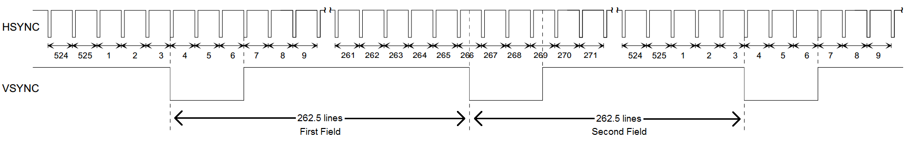
HSYNC and VSYNC waveforms representing 60Hz standard definition video. Line numbers are labeled as are the two unique fields required for interlacing.
When monochrome (black&white) television broadcasting (as defined by RS-170/EIA-170) was first introduced in North America, a scheme needed to be devised to combine (encode) all the required audio & video information into a single signal for transmission over the airwaves. One of the steps involved in achieving this was to convey the HSYNC and VSYNC information in a way such that it can be interpreted and utilized by the display device to make the final image. “Information” is very crucial to emphasize here. Video cameras and other video source equipment destined for TV* consumption do not explicitly generate separate HSYNC and VSYNC signals which are later combined into CSYNC via a separate circuit or procedure. The CSYNC signal is generated directly in a manner where the underlying HSYNC and VSYNC data can be inferred by the circuitry in the target device. The takeaway here is that the explicit HSYNC and VSYNC signals are only ever accessed at the display side.
*NOTE: This discussion focuses only within the context of television. The modern computing and PC space handles things differently, where HSYNC and VSYNC signals are explicitly generated and transmitted over a short distance to the display (e.g. VGA cables).
Generating a Practical CSYNC
The most straightforward way of doing this would be to simply widen the HSYNC pulse whenever VSYNC is active [section (A) in the figure below]. The main problem with this is that a display device loses HSYNC lock during this portion. The solution is to introduce a series of wide pulses which still have falling edges where HSYNC falling edges would occur [section (B) in the figure below]. In analog video terminology, these wide pulses are called “broad pulses” and the resulting small inverted pulses are called “serrated pulses”. This should be all that’s needed, but in order to effectively implement the interlacing scheme used by standard definition TV, we require one more tweak. Because the VSYNC is offset by half a line (i.e. halfway between HSYNCs), double-pulses at twice the HSYNC rate are introduced in the areas around and including VSYNC [section (C) in the figure below]. During the 3 line period prior to VSYNC, there exist 6 “pre-equalization” pulses. Similarly, during the 3 line period after VSYNC, there are 6 “post-equalization” pulses. Additionally, the width of these equalization pulses is half the width of the normal HSYNC pulses. The evolution of this concept along with the various waveforms are shown below.

Evolution in the design of a proper CSYNC signal for practical transmission and recovery:
(A) = Naive direct logical combination of HSYNC and VSYNC
(B) = Addition of broad/serrated pulses during VSYNC to keep HSYNC lock
(C) = Addition of double-pulses and shortened width for pre/post-equalization pulses to maintain interlacing
To validate the practicality of the finalized CSYNC waveform above, we can briefly examine simple examples* of how HSYNC & VSYNC can be recovered at the display side of the video system. Since this properly constructed CSYNC retains all of the original HSYNC’s falling edges, we can use those edges to trigger a monostable multivibrator (aka “one-shot”) to generate HSYNC pulses at their standard widths and at the correct locations. If required for a particular application, a second non-retriggerable one-shot, controlled by the same CSYNC input but with its output set just shy of the total line length (at about 95%), can be used to inhibit the output of the first one-shot in order to ignore the double-pulses during pre/post-equalization and VSYNC. For discrete VSYNC recovery from CSYNC, a simple two-stage RC integrator (filter) followed by an analog comparator set at a suitable threshold can be used to recover the wider VSYNC while ignoring all the shorter HSYNC pulses. An example circuit of this outlined VSYNC recovery method and its relevant waveforms are shown below.
*NOTE: These examples are highlighted and discussed for educational purposes only.

Simple RC integrator + analog comparator VSYNC recovery circuit.
31 Flavors of 240p
The above CSYNC timing structures describe the 525-line 60Hz system (59.94Hz for color), or “480i” as it’s more commonly known today. 240p, in its most simple representation, is a slight variation on the above timing. Instead of drawing 262.5 lines in between each VSYNC edge to achieve interlacing, the idea is to have an integer number of lines which is needed for progressive scanning (the ‘p’ in 240p). There are two main ways of accomplishing this. Game consoles, retro computers, and various other devices are known to implement either one of these two types. You can either get rid of a half-line resulting in 262 lines, or add an additional half-line bumping you up to 263 lines. Regardless of which method is implemented, each field’s timing pattern now looks exactly the same, and the concept of first/second fields no longer applies. Therefore, the term “field” is dropped and the set of lines between each VSYNC edge is known as a frame. Because of all this, even more variations of 240p manifest themselves. The double-pulses no longer serve a practical purpose, so a common variation used by video equipment manufacturers is to remove them from the pre-equalization section, VSYNC broad/serrated pulse section, and post-equalization section. On top of that, some implementations choose to also increase the widths of the shorter pulses during pre/post-equalization back to the normal HSYNC pulse width.
As you can see, it starts to get quite messy once 240p comes into play. A handful of some different possible 240p flavors are shown below. Although there are many combinations of these slight variations, not one of them is documented within a video standard. However, within most implementations of 240p CSYNC the critical properties of the timing structure stay intact, increasing the likelihood that the signal can be properly recovered and interpreted by modern television receivers. These properties include (1) having 262 or 263 total lines per frame, (2) the length between each HSYNC edge being constant from line to line, and (3) the length between each VSYNC edge being constant from frame to frame. #1 is important because although analog CSYNC was never standardized, both 262-line and 263-line progressive video are standardized in the digital CEA-861 timing specifications used for HDMI. Therefore, a modern digital display at least has a defined target digital destination it can map an incoming analog CSYNC source onto. #2 and #3 are vital because PLLs (phase locked loops) are used to regenerate the pixel clock by locking onto consistently occurring HSYNC and VSYNC edges. Any peculiarity in the position of the edges can cause the PLLs to lose lock and result in a “no signal” message, a “mode not supported” message, or a flickering screen. #2 and #3 are so important that they also apply to any input format, and aren’t exclusive to 240p.
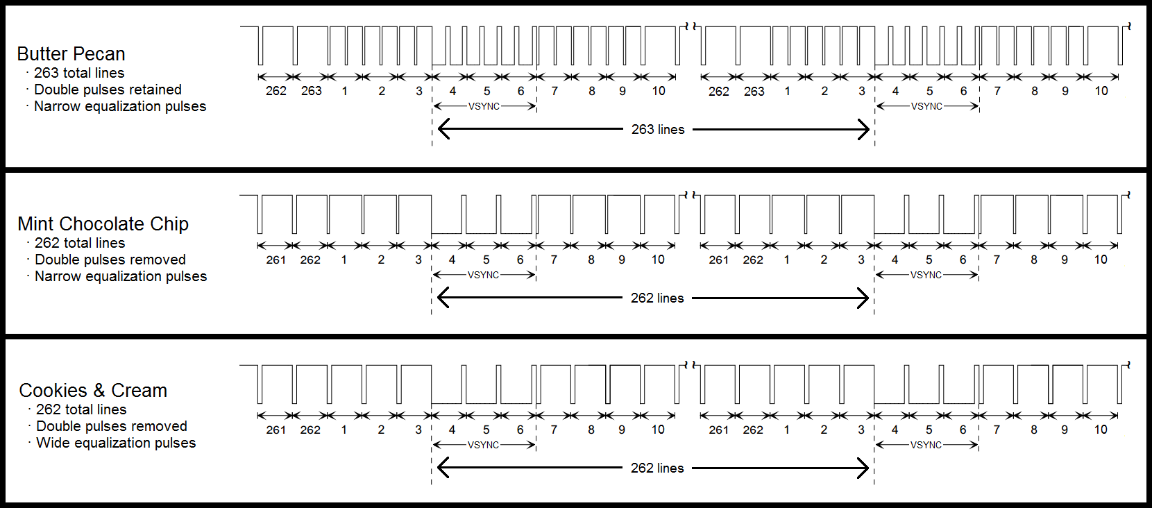
A handful of the many possibilities for 240p CSYNC. All the flavors shown here adhere to the 3 critical timing rules discussed above.
Summary
The main takeaways from Part 1 are as follows:
1.) CSYNC is typically generated directly, and not from a combination of existing HSYNC and VSYNC signals.
2.) Many properties for proper CSYNC were established specifically for interlaced television broadcasting applications. These properties are now standardized and need to be followed today even if the original technical reasons are no longer relevant.
3.) 240p CSYNC, due to its similarity to 480i, has many variations which can easily confuse display devices.
4.) Adhering to the outlined critical timing specifications as strictly as possible greatly increases the chances that no issues arise when decoding CSYNC signals, regardless of input format (i.e. 240p, 480i, 480p, etc.).
Stay tuned for Part 2 where I’ll describe common CSYNC implementations derived from explicit HSYNC & VSYNC signals which don’t quite cut the mustard. These implementations break one or more of the timing properties established above.
References
Benson, Blair, and Jerry Whitaker. Television Engineering Handbook: Featuring HDTV Systems. 2nd ed., McGraw-Hill, 1992.
Jack, Keith. Video Demystified: A Handbook for the Digital Engineer. 4th ed., Newnes, 2005.
Poynton, Charles. Digital Video and HDTV: Algorithms and Interfaces. Morgan Kaufmann Publishers, 2003.
Consumer Electronics Association. "CEA-861-D." A DTV Profile for Uncompressed High Speed Digital Interfaces, June 2006.
Electronic Industries Association. "EIA-170." Electrical Performance Standards - Monochrome Television Studio Facilities, Nov. 1957.
Society of Motion Picture and Television Engineers. "SMPTE 170M-2004." Composite Analog Video Signal - NTSC for Studio Applications, Nov. 2004.